Pulse Holography
Introduction
Holographic recording of objects using continuous-wave lasers always has limitations regarding the selection of objects to be imaged. This is because, to achieve maximum diffraction efficiency, the interference pattern must not shift by a distance comparable to the wavelength during the recording process. Such a shift can occur as a result of even the slightest movement of the photographic plate, optical components, or the object being recorded during hologram recording.
Typically, shifts occur due to the influence of external mechanical factors on the optical system and the object being imaged: vibrations, air convection, or even changes in the linear dimensions of the elements due to temperature fluctuations. This is precisely why, for recording a high-quality hologram, the choice of the type of object to be imaged is very important. The less susceptible the object’s material is to external influences, the better it is for holographic recording.
Objects made of metals with low coefficients of thermal expansion are considered ideal. For recording a metal coin, for example, the requirements for circuit stability are the lowest. But for recording a doll with many small details, including fine hairs, the requirements for circuit stability are extremely high (Fig. 1)

Fig. 1 Objects for recording with different requirements for circuit stability.
When living biological objects are used as subjects, it is practically impossible to record a hologram using continuous-wave lasers, since the interference pattern from the biological object constantly changes its distribution during the recording process. Pulsed lasers with pulse durations of approximately 20–30 nanoseconds are used to record biological objects and fast-moving processes. With such a short exposure time for holographic recording, the interference pattern does not have time to shift by an amount that significantly affects the recording of a high-quality hologram, even under strong vibrations (or even when the object being imaged is moving).
Pulsed holographic imaging is fundamentally no different from continuous hologram recording. Using a pulsed laser, one can record both transmissive and reflective holograms. However, in practice, a two-step recording scheme is most commonly used, in which a transmission hologram is first recorded according to the Leith-Upatnieks scheme, and then a reflective copy is made using a continuous-wave laser (Fig. 2).
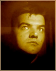
Fig. 2 Holographic monochrome portrait
(reflective copy from a transmissive original)
Currently, only monochrome pulse holograms are mass-produced using the two-step method. The color range of the finished reflective hologram varies from “green” to “red” shades.
The task of creating a setup for recording color impulse holograms is one of the promising areas of development in holographic technologies. Solving this problem will increase the realism of “portrait” holographic images and expand the list of objects that can be used for classical (non-synthesized) color holographic recording.
Two-stage scheme for recording pulse holograms
The two-stage method for recording pulse holograms consists of a stage for recording the transmissive original and a stage for recording the reflective copy. The first stage-recording the transmissive original-is performed using a pulsed laser, according to the classical off-axis Leith-Upatnieks scheme (Fig. 3)

Fig. 3 Scheme for recording the transmitting original
The optical scheme of the pulsed laser setup generates two beams: an object beam and a reference beam. The object beam illuminates the object, after which the light reflected from the object falls onto the photographic plate. The reference beam illuminates the photographic plate at an angle α with a spherically diverging wavefront. The spatial position of the divergence point X0, Y0, Z0 is determined by the position of the filtering unit’s aperture and the presence of additional optical elements used to expand the reference beam.
The object to be recorded is placed at a distance h from the photographic plate. Since the reference and object beams strike the photographic plate from the same side, the resulting recording is a Leith-Upatnieks transmission hologram that can only be reconstructed using laser light.
The second stage involves reconstructing the holographic image of the object and copying it onto a reflective hologram.

Fig. 4. Schematic of recording a reflective copy
The general principle of copying a holographic image is shown in Fig. 4. From the original hologram recorded in the first stage, a real (focused) image of the recorded object is reconstructed. To reconstruct the real image, the hologram must be illuminated by a beam that is optically conjugate to the reference beam used in the recording.
The reference beam during the recording of the original hologram was divergent and had a divergence point at coordinates X0, Y0, Z0. To obtain an optically conjugate beam, the hologram must be illuminated with a converging beam such that the convergence point coincides with the coordinates X0, Y0, Z0. The more precisely this condition is met, the more accurately the wavefront conjugate to the original will be reconstructed. Such a converging beam is formed using a large-aperture spherical mirror, which focuses the diverging beam incident on it at the desired point with coordinates X0, Y0, Z0.
The reconstructed image of the original object will be located at a distance h from the transmission hologram; a photographic plate is placed in this zone to record the reflection hologram. The reconstructed real image for the copy hologram will be the object beam. The reference beam is incident from the opposite side of the photographic plate at an angle β.
To achieve ideal reconstruction conditions, the reference beam for the copy hologram should be convergent; however, this condition is not mandatory for reasons that will be described below in the section “Continuous Copying Setup,” so the reference beam is typically formed to be parallel. The parallel reference beam is formed using large-scale optics (spherical mirrors or a combination of a lens and a plane mirror). The reference beam strikes the photographic plate from the side opposite the object beam, thereby forming a reflective hologram that is reconstructed in white light.
This two-stage scheme is used in most setups for recording pulsed monochromatic holograms; the differences usually lie in minor design features of the pulsed system and the setup for copying with a continuous-wave laser.
Pulsed System
The pulsed setup is designed to generate reference and object beams for a transmission-type recording scheme (Fig. 3) and consists of a pulsed laser and an optical beam-forming system.
Let us consider the operation of a pulsed laser using the example of the GREEN STAR laser, which is used in our pulsed system and has the following characteristics:
- Recording wavelength: 527 nm
- Pulse duration: 30 ns
- Pulse energy in gain mode: up to 2.5 J
- Pulse energy in pilot mode: 1 mJ
- Depth of the recorded scene: 3 m
The design of the GREEN STAR laser is shown in Fig. 5. This pulsed laser consists of four main functional units:
- A master oscillator based on a YLiF4: Nd
Spatial filter
Two-pass amplifier
Frequency-doubling unit and spectral filter

Fig. 5 Optical diagram of the Green Star pulsed laser [2]
Master oscillator
The master oscillator is a unit that generates an initial, low-power pulse in an active element made of a YLiF4:Nd (neodymium-doped yttrium-lithium bifluoride) single crystal. Radiation generation in the active element occurs via pumping from a gas-discharge lamp pulse, which is located adjacent to the active element. To maximize the efficiency of energy transfer from the pump lamp to the rod of the active element, the lamp and the rod are housed in a special device called a quantron.
Structurally, the quantron is an element with a hollow elliptical channel, the inner walls of which are coated with a mirror layer. The lamp is placed at the upper focus of the elliptical channel, and the active element at the lower focus (Fig. 6). This design allows the energy of the pump lamp’s flash to be effectively concentrated in the active element’s zone.
To cool the quantum, the cavity is filled with a circulating coolant solution. Distilled water or salt solutions are used as the coolant; these solutions help absorb the ultraviolet portion of the spectrum, thereby protecting the active element.

Fig. 6 Schematic of a quantron [3]
The generation of the initial laser pulse occurs in a ring resonator system containing an active element, three mirrors, a Q-factor modulator, and a Fabry–Pérotinterferometer (Fig. 7)
The system of three mirrors, 4, 4, 5, represents a variation of the classical optical resonator scheme for generating laser radiation using 100% and 50% mirrors.

Fig. 7 Master oscillator circuit [3]
The Q-switch 6 is a device that acts as an optical shutter within the resonator to accumulate energy. The basic idea is that during pumping, the Q-switch intentionally “deteriorates” the properties of the optical resonator, preventing the laser from emitting energy. As a result, energy is not dissipated into output radiation until a certain level is reached, allowing for a high level of population inversion in the active medium. Subsequently, the Q-switch “opens,” and all the accumulated energy is released as a short, powerful pulse.
The GREEN STAR laser design employs a phototropic (GSGG:Cr) Q-switch. The operation of phototropic Q-switches is based on the resonant absorption of radiation by solutions of organic dyes. These substances absorb a weak light flux almost completely, but as its intensity increases, they become nearly transparent. The parameters of the Q-switch determine the duration of the output pulse, 30 ns.
The Fabry-Pérot interferometer 7 is an optical element that transmits, without attenuation, strictly one wavelength, which is determined by the design features of the device. The Fabry-Perot interferometer is used to select the spectral composition of the output radiation, with the spectral width not exceeding ten angstroms. The wavelength of the output pulse at the optical resonator output is 1.053 μm.
Spatial filter
This unit ensures uniform intensity distribution at the amplifier input and “temporal decoupling” of the master oscillator from the depolarized component at the amplifier output, which could trigger a secondary pulse in the master oscillator.
The spatial filter is designed to produce a pure Gaussian distribution for the beam exiting the master oscillator. To achieve this, the beam diameter is first reduced by a factor of three using two lenses arranged in a Galilean telescopic system. Reducing the beam diameter by a factor of three reduces the distance to the Fraunhofer diffraction zone (far zone) by a factor of six. Afterward, a system of prisms is used to increase the optical path length to 2.5 meters. As a result, only the central maximum of the Gaussian distribution reaches the amplifier input.
Amplifier Block
The amplifier block is a system comprising an active element (Nd Glass) with a pump lamp, a WFM mirror (wavefront modulation cell), and polarizer systems for selecting the input and output radiation.
Radiation from the master oscillator enters the active element (Nd Glass rod). Structurally, the active element and the amplifier’s pump lamp, just as in the master oscillator, are housed in a quantum well with an elliptical channel (Fig. 6).
The pulses from the master oscillator and amplifier lamps are strictly synchronized, and the 1.053 μm radiation passing through the Nd Glass active element is optically amplified for the first time.
The optical amplification process is based on the same physical principle as laser radiation generation in a resonator. The pulsed excitation of the active medium by the pump lamp causes the atoms of the active medium to transition to an excited state and emit photons. Until the atom transitions out of the excited state, a photon entering it knocks out another photon, and the coherence, wavelength, polarization, and phase of these photons will be identical. If laser radiation is introduced into the active medium during this process, it will also knock out photons with its own characteristics. Thus, the input radiation is amplified.
After the first amplification, the radiation enters the BPM cell, whose primary function is wavefront inversion. Wavefront inversion is a process in which the phase of the wavefront exiting the cell becomes exactly out of phase with the incoming wavefront.
The inversion of the static wavefront can be easily achieved, for example, when reconstructing a hologram using a source that is optically conjugate to the reference source. This scheme is shown in Fig. 4; in it, the image reconstructed by the hologram in the copying scheme will be pseudoscopic (“inverted”), i.e., reconstructed in antiphase. This is one of the remarkable properties of holographic images, based on the wave properties of light.
In laser amplification systems, dynamic wavefront inversion is employed, which can be achieved using the Mandelstam–Brillouin stimulated scattering effect. Wavefront inversion returns the amplified beam back into the amplifier in antiphase. Due to wavefront inversion, all nonlinear phase distortions that the radiation acquired while passing through the active element of the amplifier are compensated, and a “clean” but already doubly amplified light beam is observed at the amplifier output. Since the radiation is amplified twice in the circuit, this amplification scheme is called a two-pass scheme. As it passes through the polarizer system, the amplified beam at the output is completely deflected into the region of the frequency-doubling node.
Frequency-doubling node and spectral filter
The amplified radiation at a wavelength of 1053 nm must be converted into visible light for hologram recording, for which a frequency-doubling node on a nonlinear DKDP (KD * P) crystal is used.
The physics of the second-harmonic generation process boils down to a nonlinear optical process in which photons of the same frequency, interacting with a nonlinear DKDP crystal, combine to form new photons with double the energy and, consequently, with a wavelength half that of the initial one.
As a result of irradiating the DKDP crystal with radiation at a wavelength of 1053 nm, second-harmonic radiation with a wavelength of 527 nm is generated at the output, which falls within the visible spectrum and is suitable for recording on photoplates sensitized in the “green” region.
A spectral filter is placed after the frequency-doubling stage to block the portion of the radiation with a wavelength of 1053 nm that has not undergone conversion.
Optical diagram of a pulsed laser system
Assembling and aligning optical systems using a pulsed laser is a rather labor-intensive process, since it is not possible to constantly verify the correct path of the beam in pulsed mode. By operating in a pilot pulsed mode , one can avoid problems associated with high pulse energy, but fully tuning the system is quite difficult. In our work, we use low-power continuous-wave lasers (typically laser pointers) to first perform a rough alignment of the entire system, and then fine-tune the system in pulsed (pilot) mode.
To ensure the best possible alignment of the beam characteristics, we use “green” laser pointers with a wavelength of 532 nm. The pointer is mounted on an alignment unit, which is used to precisely adjust the alignment of the continuous and laser beams. The alignment accuracy is verified at several points at a distance from the beam convergence point. The most precise adjustment is performed several meters away from the convergence system (a divergence of several meters is created by successive reflections in several interference mirrors). As a rule, for portrait-oriented recording, this level of alignment accuracy is sufficient for precise system adjustment.
The optical diagram of the pulsed laser setup is shown in Fig. 8. The path of the laser beams is shown schematically without magnification on the optical elements.
The pulsed radiation exits the laser source 1, is reflected by the system of 100% interference mirrors 2 and 3 (here and below, all mirrors except element 11 are interference mirrors), and strikes the semi-transparent mirror 4. Element 4 reflects 30% of the radiation and transmits 70%. Thus, the beam is split into a reference beam (30%) and an object beam (70%). The reference beam, reflected from element 4, passes through prism 5.
The purpose of Prism 5 is to rotate the spot’s orientation by 90 degrees. This is done so that a horizontally oriented spot falls onto the photographic plate. The output spot of the laser source is typically an ellipsoidal rather than a circular shape, vertically oriented. The photoplate, however, is usually positioned horizontally to increase the horizontal field of view during exposure. If the spot’s orientation is not rotated, the exposure area would need to be significantly increased to cover the entire photoplate, which would negatively affect the system’s energy efficiency. Therefore, the light spot is rotated 90 degrees using a prism so that its orientation matches the proportions of the photoplate.

Fig. 8 Optical diagram of a pulsed laser system
After passing through prism 5, the beam strikes mirror 6, then passes through lens 7 of the spatial filtering unit. The spatial filtering unit consists of lens 7 and aperture 9. This unit differs significantly in its characteristics from spatial filters for continuous-wave lasers. The focusing lens 7 has a focal length of 1 m, and the filtering aperture is approximately 1 mm in size. These characteristics are due to the very high energy of the recording pulse. When using systems with shorter focal lengths, thermal breakdown of the air will occur at the focus due to the very high energy density, which will lead to distortion of the focusing beam. And when attempting to reduce the size of the aperture, the energy that will be focused at its edges will also lead to thermal distortions in the aperture region, disrupting the integrity of the beam.
The use of a large aperture in the filtration unit makes it extremely difficult to effectively “clean” the reference beam. Therefore, cleaning the elements of dust and contaminants in pulsed systems is quite relevant. However, it is worth noting that due to the specific nature of the chemical processing of exposed photoplates by bleaching, as well as the use of a remote original placement scheme in the copying system, the distortion pattern that inevitably remains on the original after spatial cleaning does not significantly affect the quality of the resulting reflective copy.
Practice shows that after bleaching the photographic plate, those areas where interference artifacts (stripes and rings) were clearly visible have virtually no effect on the structure of the reconstructed wavefront. This occurs because the photographic material used has a sufficiently wide dynamic range, and even large-scale amplitude artifacts, when superimposed on the fine interference pattern, do not significantly affect its phase contrast after bleaching. Artifacts primarily affect the so-called relief component (variations in the plate’s relief height after bleaching); however, since this component is almost completely eliminated after applying transparent protective varnishes, the impact of artifacts is minimized.
The second feature that reduces the significance of the original hologram’s interference artifacts is a characteristic of the image copying scheme onto the reflective copy. During copying, the original is placed at a considerable distance from the reflective copy (distance h-Fig. 4). In practice, this is usually 30–40 cm. This distance is determined by the recording scheme’s parameters and cannot physically be reduced to zero due to the need to illuminate the hologram with a reference beam. When reconstructing the hologram from the copy, the object is typically located in the plane of the hologram, while the original is positioned 30–40 cm in front of the hologram. This causes any artifacts present in the original hologram to become heavily blurred and have no effect on the quality of the final image.
After passing through aperture 9, the diverging beam strikes negative lens 10, which is necessary for further expanding the reference beam. The expanded reference beam, after reflecting off mirror 11, strikes the photographic plate 12 at an angle of 40–50 degrees to the perpendicular. Thus, the reference branch is formed.
The object beam, passing through the beam splitter 4 and mirrors 13, 14, and 15, strikes the negative lens 16, after which (now expanded) it strikes the diffuser 17. After passing through the diffuser, the beam illuminates the subject 18, after which the light reflected from the subject falls onto the photographic plate 12. This forms the object branch.
The expansion of the beam as it strikes the diffuser is necessary primarily to ensure the safety of the eyes of the biological subject (humans or animals) during photography. Widening the diameter of the illuminated spot reduces the peak light pressure on the retina and, combined with bright non-actinic (red) pupil illumination, ensures the safety of the subject.
The diagram shows the most basic type of lighting-using a single light source (diffuser 17).To achieve a more artistic lighting effect, the object beam is split into two equal parts, and the object is illuminated simultaneously from the left and right. This helps avoid harsh shadows in the image and improves the perception of the object in the hologram.
A pilot source of continuous radiation (typically a "green" laser pointer) is positioned behind mirror 3 on a mount with angular (two-axis) adjustments, which are also applied to the mirrors in the circuit. The similarity in wavelengths between the pointer and the pulsed laser source allows the light to travel nearly the entire optical path to the photoplate, which greatly aids in adjusting the system.
Basic adjustment of the setup after the pulsed laser enters operational mode begins with adjusting the filter assembly (7, 9). By adjusting the rotation of mirror 8, the focused beam is directed into aperture 9. Fine-tuning is performed by moving the aperture in assembly 9 in the XY plane using the adjustment knobs. The radiation passing through the aperture is centered on lens 10, after which it expands and strikes mirror 11. Mirror 11 is adjustable both in tilt angle and rotation angle, thereby allowing the reference beam to be aligned across the surface of the photoplate.
The object branch shown in Fig. 6 is much easier to adjust than the reference branch. The main task is to illuminate the area of the diffuser 17 with a spot 50–60 mm in diameter at an angle such that the maximum amount of energy falls on the subject. As a rule, the beam is first directed at the object without the diffuser, and then the diffuser is placed in the beam path. Frosted glass with varying degrees of diffusion is used as a diffuser, depending on the nature of the imaging.
Adjustment using a continuous-wave laser significantly simplifies the process; however, the final adjustment must be performed only in pulsed mode. A pilot power of 1 mJ allows the undiffracted pulse spot to be seen quite clearly, even under normal lighting conditions. However, when adjusting the spot to the size of the photographic plate, the room must be completely darkened; otherwise, a spot measuring 30 × 40 cm will be difficult to see.
Assembling and adjusting the pulsed setup circuit requires some experience; however, if the circuit has already been assembled and adjusted for specific recording conditions, then during a restart, only the most minor adjustments are required, which usually boil down to adjusting the focal point for aperture 9 and adjusting the spot to the area of the photographic plate using mirror 11.
The photographic plates used for recording transmission holograms are high-resolution FP-R photographic plates with a high silver content, manufactured by Slavich JSC. The photographic plates have high sensitivity (75 μJ/cm²) and are coated on the glass side with an anti-halation red layer (to reduce stray reflections).
Before exposure, the plates are placed on the screen with the emulsion side facing the object, after which the recording pulse is applied. Given the relatively high cost of FP-R photographic plates, it sometimes makes sense to perform a test recording before the main exposure. To do this, one of the plates is cut into 5×5 cm squares, and a test exposure is performed, followed by development. It is important to note that it is highly desirable for the test plates to be from the same batch as the main ones, since the properties of photographic plates change significantly over time.
The chemical processing of exposed photographic plates includes development, fixing, bleaching, and drying. The development and fixing procedures are carried out under non-actinic, red lighting.
After exposure, the photographic plate is placed in a bath of SM-6 developer, where it is developed for about 10 minutes at a developer temperature of 38 degrees. To maintain the desired temperature during development, the developer bath is placed in a second bath of water, the temperature of which is 2–4 degrees higher than the development temperature. After immersing the photographic plate in the developer for 1 minute, the plate is gently agitated to ensure uniform wetting of the surface, and then covered with a lid to prevent accidental exposure.
After development is complete, the photographic plate is thoroughly rinsed in running water and then placed in a bath of acidic fixer for 10 minutes. After fixing and thorough rinsing, the photographic plate is placed in a bath of bleach (ferric chloride), where it remains until complete bleaching (complete disappearance of black areas). The bleaching procedure is performed under normal lighting. After bleaching, the plate is rinsed under running water and soaked in a bath of surfactant (a standard Fairy-type detergent-2 ml per liter). After that, the hologram is placed in a drying cabinet, where it remains until completely dry. The final processing step after drying is the application of acrylic varnish to the emulsion side (using a spray can). It is especially important that no dust or foreign contaminants come into contact with the applied varnish before it dries. The varnish provides good protection for the emulsion against damage, but its main purpose is to eliminate surface relief noise, which reduces the contrast of the holographic image.
A chlorine-iron-based bleach has excellent signal-to-noise ratio characteristics on the finished hologram compared to other bleaches (based on amidol or iodine), but it has one drawback. Holograms bleached in a chlorine bleach solution darken very quickly when exposed to light with high levels of ultraviolet radiation (for example, in direct sunlight). Since the originals are primarily used in dark rooms after processing, this is not a significant drawback; however, it is best to store the originals in the dark after bleaching and varnish protection.
After all these steps, the finished hologram the original is placed in a copying machine to create a reflective copy. Figure 9 shows photographs of some images restored from the original holograms using laser light.
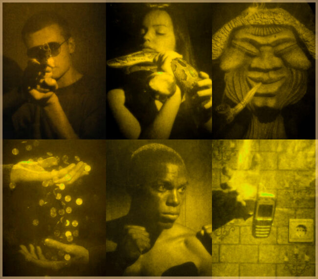
Fig. 9 Images of pulsed originals captured in laser light
Continuous copying unit
The copying setup is designed to create a reflective copy from a transmissive original recorded on the pulsed setup. The need to create a reflective copy arises because the Leith-Upatnieks transmissive hologram, which was recorded in the first stage, can only be reconstructed using a laser source.
In addition, recording a transmission hologram requires the object to be located a significant distance from the hologram plane, and the reconstruction of deep holographic scenes imposes special requirements on the reconstruction sources.
The requirements for the size of the hologram reconstruction source directly depend on the distance between the object and the photoresist plane. The closer the object is to the hologram, the less point-like the source must be. This characteristic is explained by the fact that a single point light source reconstructs a single image, whereas a diffuse light source, such as a matte lamp, reconstructs an array of images shifted relative to one another, which leads to image blurring. This shift is determined by the difference in angular dimensions of the extended source and depends on the distance from the hologram to the object. Therefore, the farther the object is from the hologram, the greater the image blurring will be. For example, when recording a coin with fine relief pressed tightly against the photographic plate using the Denisyuk method, the requirements for the reconstruction source will be minimal. In fact, the hologram will reconstruct such an image without blurring when illuminated by light from a source of any size. However, if the object, as in the case of recording using the Leith-Upatnieks method, is distant from the surface of the hologram, the requirements for the size of the reconstruction source increase sharply. To mitigate this factor, in the continuous copying scheme, the object is moved close to the plane of the photographic plate (see Fig. 4), after which the requirements for the size of the reconstruction source are significantly reduced.
In addition, sometimes when moving the scene, some objects end up “in front of” the hologram. Practice shows that the psychological effect of perceiving an object “floating in the air” is extremely strong, which positively influences the overall perception of the scene.
The copying setup we use is equipped with a continuous-wave “red” He-Ne laser. Currently, there are many modern laser sources of various wavelengths, which eliminates the problem of selecting a continuous-wave laser with a wavelength close to that of the pulsed laser on which the original hologram was recorded. In addition, a number of high-quality photographic materials have already appeared, including full-color ones, which can be recorded at both “red” and “green” wavelengths.
However, during the development of our system for pulsed exposure and continuous copying, the challenge of selecting a compatible laser/photomaterial combination was very pressing. At that time, “green” wavelength lasers were typically based only on argon and krypton tubes. They had sufficiently high output power but required a high- -power supply and water cooling. Furthermore, the only high-quality holographic material available at the time the system was developed was the PFG-03M silver-halide photoplates, mass-produced by the Mikron plant (Slavich JSC, Pereslavl-Zalessky). PFG-03M photoplates are sensitized to red light and require the use of “red” laser sources. At the time the system was developed, there was a wide range of high-quality He-Ne (“red”) lasers with power up to 60 mW, which did not require water cooling and had low power consumption. All of this led to the use of a “red”He-Ne laser (633 nm) with a power of about 60 mW and a spatial coherence length of about 0.4 m as the laser source in the copying system.
The difference in wavelength between the recording source and the source reproduced during copying resulted only in the image being slightly reduced (~1.15x) due to the wavelength difference. The Leith-Upatnieks hologram, lacking spectral selectivity, perfectly reconstructed the original wavefront, and the difference in size during copying was practically imperceptible to the naked eye.
In addition to the convenience of using red lasers and the availability of high-quality photographic material, recording in the red region had an advantage in creating holographic portraits, since the red region was psychologically perceived slightly better by humans than the green region. Furthermore, it turned out that by using a specific type of chemical processing involving significant shrinkage of the photographic emulsion, the spectral range of the reconstructed image could be shifted toward a “golden” hue, which was also positively perceived by the observer.
Optical diagram of the copying setup
The copying setup diagram is shown in Fig. 10. Laser radiation emitted from the Ne-Ne laser 1 passes through a mechanical shutter 2, which opens during the exposure, is reflected by a 100% interference mirror 3, and passes through a half-wave plate 4.
The half-wave plate is needed to rotate the polarization angle of the laser radiation. By adjusting the angle of the polarization plane, parasitic reflections during hologram recording can be reduced.
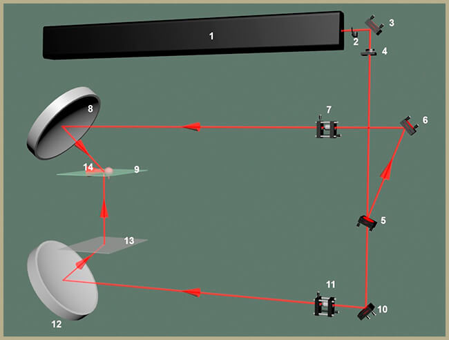
Fig. 10 Copying setup diagram
Next, the beam strikes element 5, which is a semi-transparent interference mirror. Here, the beam splits into a reference beam and an object beam. The intensity ratio of the reference and object beams is typically 30% for the reference beam and 70% for the object beam. Smooth adjustment of the percentage of reflected light is possible by increasing or decreasing the reflection angle of element 5.
Next, the reference beam is reflected by mirror 6 and strikes the spatial filtering unit 7, where it is “cleaned” and expanded. The expanded beam strikes spherical mirror 8 and illuminates the photographic plate with a converging beam at the recording angle. This forms the reference branch.
The object beam, after passing through element 5, strikes mirror 10 and passes through the spatial filtering unit 11. The expanded beam strikes the spherical mirror 12 and illuminates the original hologram 13 with a converging beam. The original hologram reconstructs the real image of the object 14 in the plane of the photographic plate 9. This forms the object branch.
All elements of the optical system are rigidly mounted on a steel frame. The system’s sensitivity to external vibrations is minimized both by its design features and the presence of damping shock absorbers.
The spherical mirror 8 can be replaced by a combination of a large-aperture, long-focus lens producing a collimated beam and a flat mirror. This will reduce the cost of the design and lead to a slight widening of the field of view of the reflective hologram.
The fact is that if a reflective hologram is recorded using a flat beam rather than a converging beam, the conditions for ideal reconstruction will be violated during hologram reconstruction, resulting in scale distortions in the reconstructed image. For an object located in the plane of the hologram, these distortions will be quite insignificant; however, for the area of the original hologram-which is reconstructed at a considerable distance in front of the hologram and effectively serves as an “observation window”-the scaling will be noticeable, the “window” will be enlarged, and this will have a positive effect on the field of view of the reflective hologram.
Fig. 11 shows the actual design of the GU-03 continuous copying system, developed by A. Akilov (Yaroslavl) and delivered to Novosibirsk in 2000.

Fig. 11 Photo of the GU-03 copying system (Novosibirsk)
The design of the system allows for wide-range adjustments of the optical copying scheme elements and enables the recording of reflective holograms up to 30 × 40 cm in size.
The adjustment of the mirrors forming the reference and object branches, as well as the spatial filtering units, was achieved by shifting the ring assemblies 2 (Fig. 11), which move freely along vertical guides 3. The position is fixed by clamping screws located on assembly 2.
The frame stands on three jacks 4, which supported the setup until the copying process began. Before shooting, the jacks were lowered, and the setup rested on six air shock absorbers (10 basketball balls inflated to 1.5 atm are used), which compensated for vibrations from the floor surface.
The lower spherical mirror 5 is mounted on the frame. It can be rotated to adjust the angle of reconstruction of the original hologram 6. The photographic plate is mounted on a metal frame 7, which is rigidly fixed to the system with a flat mirror 8. The entire system-photoplate/mirror-moves freely along vertical guides using a special suspension jack 9. By adjusting the distance between elements 6 and 7, the required focus zone for the object being reconstructed can be achieved.
The choice of the focus zone was, as a rule, arbitrary and was made based on the choice of artistic composition. It is extremely difficult to visually track the focus position of a three-dimensional object, since during restoration, a pseudo-scopic (inverted) real image of the object is visible. However, by placing a white paper screen in the frame instead of the plate, one can judge the current focal plane of the scene by the sharpness of individual elements.
In the case of a portrait, the focal plane most often fell on the subject’s eyes (whether human or animal). An extremely bright glare is always observed in the eye’s focal zone due to spherical reflection, so focusing on the eye area is the simplest method.
Before exposure, after the laser has been brought to operating mode and the support jacks have been removed, the photographic plate is mounted in the holder, after which the system is allowed to settle for approximately 10 minutes to dampen vibrations. Exposure then takes place. The shutter is opened via remote wired control to minimize potential mechanical and convective effects. The exposure time is approximately 180 seconds. Upon completion of the exposure, the photographic plate was placed in a darkroom and sent for chemical processing.
The chemical processing of PFG-03M photographic plates consists of development and fixing. Development is carried out using GP-3 developer for 7 minutes at 22 degrees Celsius until a bright holographic image appears on the photographic plate; signs of its appearance can be seen by viewing the hologram against the light using a point-source, non-actinic “green” light. If the hologram appears bright when viewed against the light, this guarantees that the final result will also be very bright. During development, the hologram is constantly agitated in the bath, and after development is complete, it is thoroughly rinsed with running water. The next step is to fix the hologram in a neutral fixer for 10 minutes, followed by another 10-minute rinse under running water.
The final stage of hologram processing is alcohol drying of the gelatin emulsion. This is a very important process for achieving a high-quality result. The hologram is immersed for 2 minutes each in 50% and 96% ethyl alcohol solutions. Upon completion, large contaminants must be removed from the emulsion surface using 96% alcohol and a large "squirrel" brush, after which the hologram is placed in a drying cabinet. If the hologram was not properly treated with alcohol, or if the alcohol concentration dropped significantly below 96%, colored streaks may appear on the finished hologram, severely reducing image quality.
After drying, the hologram is coated with black acrylic paint, dried, trimmed, and inserted into a decorative frame (Fig. 12)

Fig. 12 Holograms in frames with a mirror lighting system.
Recording holograms of fast-moving processes
Recording of pulse holograms - originals using objects moving through space - allows for the creation of artistic holograms with highly dramatic scenes.
The maximum object movement speed during recording, according to [1], for recording conditions of λ = 527 nm and a pulse duration of Δt = 30 ns, is approximately 6 m/s, which is quite sufficient for recording objects falling freely from a low height.
The main challenge in photographing moving objects is precisely timing the laser pulse. Given the considerable complexity of recording and developing holographic plates, as well as their high cost, a system was needed that would minimize the percentage of failed dynamic shots.
The mechanism for automatically triggering the pulse during recording consists of a continuous-wave laser–photodetector system placed in the area where the falling object is captured (Fig. 13).
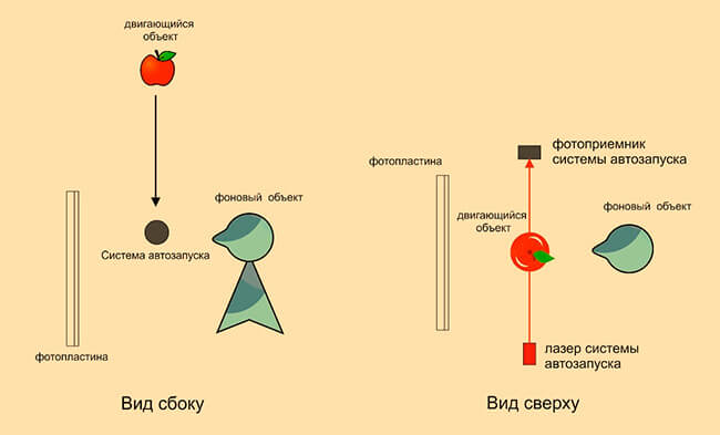
Fig. 13 Schematic of the auto-trigger system layout.
In the pulse laser control system, a relay is connected in parallel with the trigger button; this relay closes when the laser beam-photodetector circuit is interrupted. The object being captured, in free fall as it passed through the auto-trigger system, interrupted the beam, closed the relay, and triggered the capture pulse. The height from which the object fell was 1 meter above the scene being recorded, which ensured that the maximum permissible speed was not exceeded.
Fig. 14 shows two scenes captured during testing of the auto-trigger system. Fig. 14 (left) shows a scene in which a metal ball 2.5 cm in diameter falls into a glass of water. The hologram captured the ball entering the water and the formation of an air channel in the water. Fig. 14 (right) shows the moment when the ball has completely passed through the water in the glass (you can see how the air channel at the top begins to close, and the glass begins to shatter at the bottom). A large circular splash above the glass is also visible. The difference between the first and second scenes lies in the height of the object before the start of free fall (1.2 m and 0.8 m).

Fig. 14Two holograms of a metal ball, 2.5 cm in diameter, entering a glass of water
during the entry phase and during the passage to the bottom with the start of the glass’s destruction
Fig. 15 shows several artistic scenes in which the auto-start system was used. The scenes mainly involved a combination of a small falling object, which during recording was “brought in front of the glass,” and some background composition.
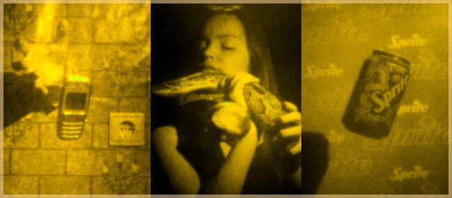
Fig. 15 Scenes using the auto-start system.
Scenes such as “Phone” or “Eva” (Fig. 15) were very popular and left a strong emotional impression on the viewer. The “Phone” hologram was produced in both full-size (30×40 cm) and 13×18 cm formats. Given the overall depth of the scene and the phone’s position in front of the glass, this format was very effective.
Combined holograms
In the process of creating pulsed artistic holograms, various approaches are used to enhance the emotional impact of viewing, including methods of combined holography, in which several holographic images are superimposed on a single hologram.
Image superposition method
The essence of the superposition method boils down to the fact that two three-dimensional images from different transparent originals are recorded onto a single reflective hologram. The manufacturing principle involved the contact superposition of the two originals (one superimposed on the other) and their joint reconstruction in the copying setup.
This method was made possible by the low noise level of the original holograms and, consequently, their high transparency. The undiffracted beam passing through the first original freely reconstructed the image from the second original; the difference in brightness between the reconstructed images was generally not perceptible to the eye. Furthermore, by changing the order of the originals depending on the subject, one could select the optimal brightness ratio between the first and second subjects.
As a result, two spatially intersecting scenes appeared in the focal plane of the copying setup, creating a new composition. Figure 16 shows two superimposed holograms, “Financial Rain” and “Paris,” for each of which two originals were recorded.
For the “Financial Rain” hologram, the first scene consisted of two outstretched hands against a black background, while the second scene contained a cloud of falling coins. The “cloud of coins” was captured in flight using a pulse auto-trigger system. As a result, the reflective hologram shows hands through which the falling coins fly.
For the “Paris” hologram, a portrait of a girl was superimposed on a flat background showing the Eiffel Tower in Paris. The background is located at a considerable distance from the portrait.

Fig. 16 Superimposed composite holograms
The “Financial Rain” and “Paris” scenes clearly demonstrate the possibilities of spatially intersecting three-dimensional scenes for artistic purposes.
Two-view holograms
Another type of combined hologram is the two-view hologram, in which two three-dimensional images are separated from each other and can be viewed by the observer from two different horizontal angles.
These holograms are made from two original holograms. Unlike combined images, the originals do not overlap but are placed side by side. To fit both originals into the copying setup, they are cut in half, and the two halves are combined into a single composite hologram, with the left-view original on the left and the right-view original on the right (Fig. 17).

Fig. 17 Combined two-view holograms
As a result, the field of view of the reflective hologram copy is divided into two zones, each of which displays its own three-dimensional image. As the viewer moves between the zones, there is a smooth transition from one three-dimensional image to another.
This technique allows for the addition of extra dynamics to the artistic composition, which also enhances the hologram’s visual impact.
Shadow Shift
The third type of combined hologram, which is used in a two-step recording scheme for reflective holograms, is shadow projection.
The problem of "projecting" objects in front of the hologram always faces the limitation of the object’s size for projection. If, for any reason, part of the object’s image "in the air" in front of the hologram is cropped by the edges of the photographic plate, the effect will be lost, and the observer will no longer see the object "in front of the hologram." Therefore, to demonstrate “projected” images, it is essential that the size of the object to be projected be slightly smaller than the dimensions of the photographic plate. Moreover, the farther the object is placed “in front of” the hologram, the smaller that object must be. This is precisely why most holographic scenes are placed “behind the glass,” projecting only a small part of the scene into the pre-screen zone and thereby losing a significant portion of the psycho-emotional impact on the viewer.
The method of adding a flat image “hanging” in front of the glass against the backdrop of a three-dimensional holographic scene was developed to maximize the emotional effect that the observer receives from the pre-screen image. This method was used in situations where the structure of the scene, for whatever reason, did not allow a significant portion of the image to be brought forward in front of the hologram.
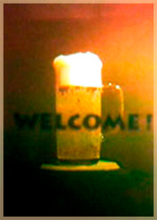
Fig. 18: Scene with a three-dimensional setting and shadow rendering
An example of such a scene is shown in Fig. 18. A beer mug on a black background was commissioned by a beer bar as a decorative element for the entrance. The composition specified in the technical assignment (a standard mug on a glass surface, a white base, and a black background) did not contain any elements that could showcase all the qualities of a holographic image.
As a result, two versions were created: one featuring only the mug, which slightly protruded from the glass, and another in which the shadow inscription “WELCOME” was visible 30 cm from the glass. The emotional impact the viewer experienced when viewing these two versions was so different that the client found the modified version more interesting.
The shadow effect is created by applying an opaque mask directly to the original hologram during the copying process. The mask is a flat image that is printed with black ink on a transparent film using a printer and placed over the original during copying (Fig. 19). As a result, on the finished hologram, a shadowed area appears in front of the three-dimensional scene at a distance h, precisely matching the shape of the mask during recording.

Fig. 19 Diagram of shadow projection creation
One of the most important features of this method, aside from the emotional effect it creates, is that no additional holographic master needs to be recorded to replace one shadow symbol with another. By using a single holographic background and changing only the shape of the shadow mask, it is possible to create holograms with different informational elements, which solves the problem of producing a cheaper series of copies with different content.
Reconstruction of Reflective Holograms
For high-quality reconstruction of images recorded on a reflective hologram, two basic conditions must be met:
The geometric conditions for reconstruction must correspond as closely as possible to the conditions that were created during the recording process.
The size of the recovery source’s emitter must be as small as possible to prevent blurring of the recovered image.
Ideal reconstruction conditions are determined by the position of the reference source in the reflective copy recording setup. As mentioned above, the ideal scenario is one in which the reference beam is convergent during recording. In this case, the reconstruction conditions will be ideal for divergent sources, which include all classical reconstruction sources (incandescent lamps and high-power LEDs). If the reconstruction conditions do not match, scale distortions will be observed in the holographic images. The magnitude of the distortions will depend on the depth of the scene and will be very noticeable on objects located far in the background or brought forward.
On the GU-03 setup shown in Fig. 11, the reference beam is parallel; therefore, for ideal hologram reconstruction, an equally parallel beam will be required.
A parallel or collimated beam can be obtained by placing the light source “at infinity.” In optics, collimated beams are formed by placing the light source precisely at the focal point of an optical lens. In nature, the sun is a natural collimated beam.
Obtaining a collimated beam when reconstructing a reflective hologram is a task that will require considerable effort. However, depending on the depth of the recorded pattern, simply moving the reconstruction source to a certain finite distance is sufficient to reduce visible distortions. The required distance of the source is determined empirically and is usually equal to three times the depth of field.
The source divergence angle must ensure that the light spot covers the entire area of the hologram, and the source power must provide the necessary brightness of the holographic image.
The angular size of the source’s beam must be as small as possible to ensure accurate reconstruction of the holographic image. As the angular size of the source increases, the hologram begins to reconstruct not a single image, but an entire array of images shifted relative to one another by the angular size of the beam. Significantly increasing the distance between the source and the hologram reduces the angular size of the filament and minimizes image blurring.
When using conventional light sources with a thermal filament, such as spot incandescent lamps or halogen lamps with reflectors, the degree of blurring at close distances will be very significant. Therefore, high-quality hologram reconstruction using such sources is only possible when they are stationary and located at a considerable distance.
In recent years, thanks to the emergence of ultra-bright single-chip LED sources of the CREE XM-L T6 class, which feature an extremely small light-emitting crystal and a massive luminous flux, the problem of hologram reconstruction using a point source has been solved. Due to the use of a lens integrated into the LED, the divergence angle of LED-based sources can be adjusted by moving a single external short-focus lens, which has significantly simplified the projector’s design.
In some cases, for example, when it is impossible to install stationary interior light sources in a room, the task arises of placing the reconstruction source directly on the hologram. When creating such designs (Fig. 20), we encountered the aesthetic challenge of positioning the rod with the light source on the hologram.

Fig. 20 Placement of a removable rod with a halogen lamp and power supply on the hologram
The rod with the light source could not be placed in close proximity to the hologram, as this introduced distortion and blurring into the holographic image, while placing the rod significantly farther from the hologram resulted in a loss of the system’s ergonomics, which was intended to blend harmoniously into the existing interior.
One solution to this problem, which we implemented technically, is to optically increase the distance to the light source using a flat mirror.

Fig. 21 Lighting system with a mirror
Light from the source is first directed onto the mirror, doubling the optical path as a result of reflection. The result is a fairly compact design (Fig. 21) compared to the design with a remote source on a rod. The source and mirror are mounted on flexible brackets to allow for free adjustment of the angle of the light fixture and the mirror.
Psycho-emotional perception of holographic portraits
When observing holographic images of people (holographic portraits), for a certain, fairly large proportion of observers, holographic portraits evoke strictly negative emotions. In an attempt to understand the reasons behind this phenomenon, we found a theory whose description fits very well with the symptoms we sometimes observed in people when viewing holographic portraits. This theory is called the “Uncanny Valley” and describes a negative dip in the emotional perception of objects that are quite similar to a living human.
Human-like robots, or realistic animations created, for example, in computer games, evoke positive emotions in the observer. And as “human-likeness” increases, this empathy grows. However, this only happens up to a certain limit. As can be seen from the graph in Fig. 22, once “human-likeness” becomes very high, a person suddenly begins to perceive such an object negatively.
The reason for this phenomenon is currently unknown. Most hypotheses boil down to a person’s subconscious perception of a threat from an object that is not human, even though it closely resembles one.

Fig. 22 The "Uncanny Valley" Effect
People realize on a subconscious level that the object is not alive, picking up on even the slightest deviations from normality. In attempting to apply this theory to people’s negative perception of a holographic portrait, we sought to understand exactly what causes the emotional response to “fail” and how this can be addressed.
The first presumed factor is the absence of color. Monochrome holographic portraits undoubtedly differ in color from a living person. It has also been conclusively established that “green” portraits are perceived much more negatively than red or orange ones. The use of color recording for portrait photography should, in theory, resolve this issue and make holographic portraits more positively perceived.
The second presumed factor is stillness. In everyday life, when interacting with living people, we never see a completely still face. Even the face of a sleeping person always exhibits some degree of movement. Addressing this issue is quite challenging, as it essentially involves animating a three-dimensional image.
To combat the stillness effect, the following approach could theoretically be used. Shifting the reconstruction source results in a slight shift in the reconstructed holographic image. If a system is designed in which the source moves smoothly and mechanically along the horizontal axis over a short distance, the image of the person will also move smoothly within a small range. Perhaps such an approach could resolve the stillness problem, and the perception of the holographic portrait would be more positive.
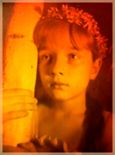
Fig. 23 S. Vorobyov’s hologram “Birch Tree”
While working on the creation of holographic portraits, we attempted to determine whether there are any artistic techniques that could mitigate the negative perceptual effect. It was observed that a portrait with some artistic surroundings is perceived more favorably by people than a portrait on its own (although no precise studies have been conducted).
Fig. 23 shows, in our opinion, one of the most successful artistic compositions of a holographic portrait - the hologram “Birch Tree” by the VVC Studio (S. Vorobyov, Moscow). Most people perceived this portrait positively, possibly due to the presence of a large number of artistic details. However, it cannot be claimed that negative emotions did not arise at all in anyone while viewing it; nevertheless, the majority of reviews were positive.
For our part, we attempted to introduce the following idea into the concept of portrait photography: If we cannot technically increase the “human-likeness” of the portrait, then perhaps it is worth slightly reducing it?
To implement this idea, a portrait hologram, for example, must be created using a combined method with image alignment. That is, the three-dimensional image of a person must be aligned with a certain three-dimensional scene, after which the image of the person in the hologram would transition, figuratively speaking, from the “corpse” category to the “ghost” category. This happens because by adding a second three-dimensional scene, we make the portrait somewhat translucent and thereby shift along the graph (Fig. 22) from the “uncanny valley” to the left, toward less resemblance to a real person.

Fig. 24 Portrait and the “Paris” combined hologram
An example of such an attempt to avoid negative perception by reducing the degree of “human-likeness” was made in our combined hologram “Paris.” Fig. 24 shows the holographic portrait and its combined hologram. In the combined hologram, due to the transparency of the portrait, the negative perceptual effect, as we assume, is completely eliminated. To confirm this hypothesis, tests on a large sample of observers are needed.
Summary
The project for recording portrait-style impulse holograms was launched in Novosibirsk in mid-2000 and remained active until 2008. In fact, the launch of this large-scale project marked the beginning of our company’s creation and development in the field of applied holography.
During its operation, a large number of pulse holograms depicting a wide variety of subjects were created. The production of serial batches and the release of custom projects were successfully established.
Unfortunately, the portrait project was unable to achieve a sustainable break-even point, particularly due to the “Uncanny Valley” effect; furthermore, the emergence of digital methods for recording full-color holograms (holographic printers) reduced the relevance of impulse technology for consumers. The project was finally shut down in 2008.
Bibliography
1. Colier, R., Burkhardt, K., Lin, L. Optical Holography: Translated from English. Edited by Y.I. Ostrovsky. Moscow: Mir, 1973. 686 pp.
2. Akilov, A., Shevtsov, M., Holography for the Curious, 2018.
3. www.holography.ru